
A new addition to my elevator was a light tree. I wanted floor indicator lights like everyone is used to seeing in an elevator (but I did not put in any buttons to control the elevator). I did not want to have just lights. When the elevator gets drageed down to Hell, I wanted the indicator lights to follow the decent with red skull lights appearing out of nowhere.
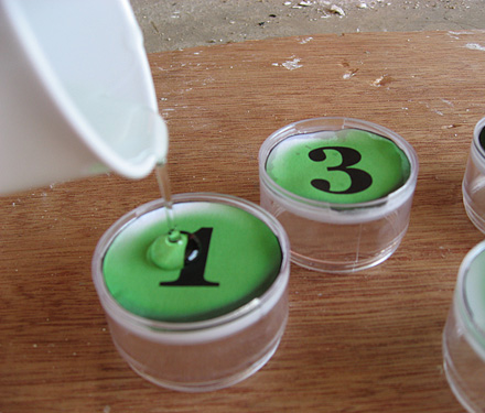
First thing I needed was to make the visible lights. I found some cylindrical plastic boxes (1.5" in diameter) at a craft store indended to store beads. I made a 1, 2 and 3 on a green background (using Photoshop), cut them out and glued them to the back of the boxes. I then poared some clear arylic over the numbers to make them look like glass. I had a 1.5" bore so I could easily cut some circles out of some 1/4" plywood and put a green LED at the center. Hot glue the plywood at the top of the box and I've got floor lights.

I found that the light from the LED blead through too much so I bought some foil tape used to wrap dryer vents (Home Depot), cut a strip in half and wraped it around the edges. It isolated the light much better.

Now I needed a few more complicated buttons. I needed a split arrow up/arrow down button to indicat if you are going up or going down. For that one, I made a green triangle pointing up and a red triangle below it pointing down and put them on a black backround. I printed out two copies. One I used for the button face and the other I used as a guide to cut two trianges out of a piece of the foil tape I wraped the other buttons with. I carfully attached the foil tape, now with two triangular holes in it to the back of my button face so that the triangles alligned. I also put some foil tape on a 1.5" piece of cardboard and insterted the cardboard inside the box to separate the two indecator lights. I put two LEDs in that one, one green and one red on opposite sides of the cardboard separator.
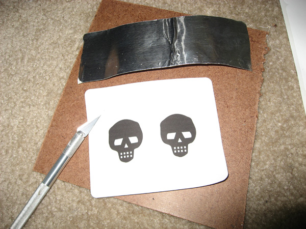
My next buttons are invisible at first, but show up as red skulls when lit. I made a skull stencil from some clip art and printed it on a lable. I then attached the stencil to some foil tape. Useing the stencil as a guild, I used a razor blade to cut out the skull.
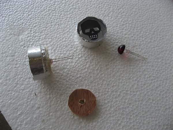
I then attached the skull tape to the front of the pill box, wrapped it in foil tape and put a ultra-bright LED in the back. Yes, I made a red acrylic lens for the LED but I don't think you need that. A small drop of hot glue on the tip of the LED should act good enough as a diffuser. I made five of these.
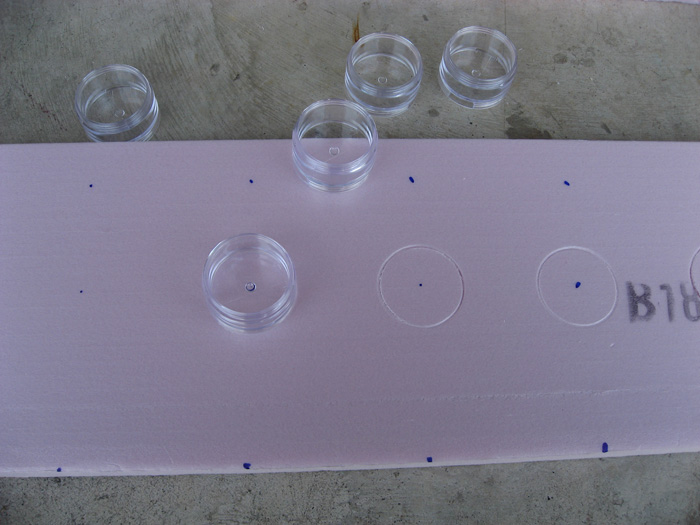
So, now I need the light board. I used a single piece of 3/4" foam board which I would eventually paint to look like wood. I marked 4 evenly-spaced dots in the center of the board and used the pill boxes to mark a circle. Carfully cut out the circle with my 1.5" bore and, as the pill boxes were just larger in diameter than 1.5", I could just push them through for a snug fit.
Here is what it looked like when I was done (picture installed in the elevator).

For the skull lights, I marked the back of the foam board with my pill boxes then used my dremel (with a flat router attachement) to carfully cut out a disk, without breaking through the front of the board. I left about 1/4" to 1/8" of foam. I then pushed the light into the routed hole. After wireing up the lights, the back of the board looked like this:

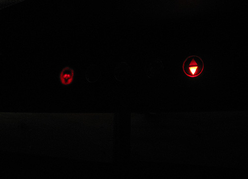
But, you cannot see the skull lights until they are lit.
We now have a lot of lights to control (10 LEDs in this chain, in fact). How do you do that in a nice computer-controled fashion? Pretty easy, actually. It is time to talk about wiring, prop controllers and programming. This is where some of you throw up your hands and leave. Don't. It is not that hard and I can help. If you can make an ashtray out of Legos, then you can do this. Sorry for those of you who have done this before, I will assume this is your first time with this stuff.
Step 1: Wiring. The wiring is simple. They all share the same ground, but each light has its own positive lead. A schematic looks like this:
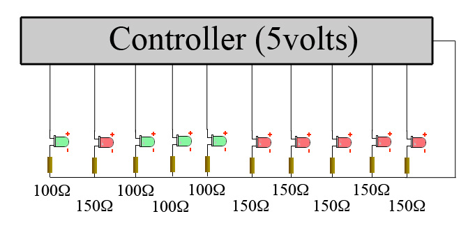
Each LED has a resistor attached to the negative lead (the shorter one) and the type of resistor depends on the color of the LED. The green ones get a 100 ohm resistor (1/4 or 1/2 watt is fine) and the red ones get a 150 ohm resistor. All of the negative leads and connected together and attached to the controller's ground. The positive leads connect to the controller in a way I will describe later. Soldering is as easy as it gets here. Just twist the wires together and put a glob of solder on.
Step 2: Prop Controller. It is now time to introduce prop controllers. There are several out there and they all have pros and cons. For the elevator lights, I like the Prop-1 or Prop-2 from EFX-TEK. They are small and stand-alone so you can program it to do what you want, then detach it from your computer and hide it anywhere. Much better than having to deal with a laptop computer during Halloween night.
So, let's simplify things a bit and rather than controlling 10 lights, say you only want five. That is perfectly reasonable for a Halloween elevator. You can use either the Prop-1 or the Prop-2 and hook it up like so:
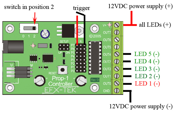
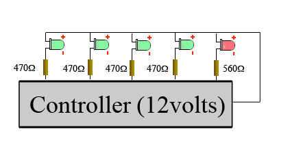
You should notice that in this simpler case, I flipped things on you and the LEDs share the positive lead and are controlled individually by the negative leads. The negative leads still have their resistors attached in between the controller and the LED but, since the voltage is greater the resistor values upped to 470 and 560 ohms. OK, just in case you don't follow, here is a schematic for the simpler version:
By the way, the trigger is attached to P7 (which ties up OUT7) and OUTs 5 and 6 are free for whatever.
The parts list for the electronics for this smaller elevator system is as follows:
| 4 | ultrabright LEDs (5mm, green) | about $1.00 each |
| 1 | ultrabright LED (5mm, red) | about $0.50 each |
| 4 | 1/2 watt 470 ohm resistor | about $0.20 each |
| 1 | 1/2 watt 450 ohm resistor | about $0.20 each |
| 1 | switch | about $1.00 |
| 1 | 1 or 2 amp 12VDC adaptor | about $10.00 |
| 1 | small prop controller | about $40.00 |
So, you can play with automation for about $60 (assuming you already have a computer for the programming interface).
Step 3: Programming. Speaking of programming, here is a program written in Basic Stamp (free software from Parallax, Inc.). This program will light the ground floor light as it waits for a trigger. After the trigger, the red down arrow lights and the green floor indicators light sequentially.
' {$STAMP BS1}
' -----[ Program Description ]---------------------------------------------
' Sample control of halloween elevator
' -----[ I/O Definitions ]-------------------------------------------------
SYMBOL Trigger = PIN7 ' SETUP = DN
' -----[ Constants ]-------------------------------------------------------
SYMBOL timer = B3
' -----[ Initialization ]--------------------------------------------------
Reset:
PINS = %00000010 'ground floor LED lit
DIRS = %01111111
' -----[ Program Code ]----------------------------------------------------
Main:
timer = 0 ' reset timer
Check_Trigger: 'wait for trigger signal
PAUSE 5
timer = timer + 5 * Trigger
IF timer < 100 THEN Check_Trigger
PINS = %00000011 'down arrow and ground floor lit
PAUSE 2000
PINS = %00000001 'down arrow only lit
PAUSE 600
PINS = %00000101 'arrow and basement floor lit
PAUSE 2000
PINS = %00000001 'down arrow only lit
PAUSE 600
PINS = %00001001 'arrow and basement 2 lit
PAUSE 2000
PINS = %00000001 'down arrow only lit
PAUSE 600
PINS = %00010000 'basement 3 lit only
PAUSE 10000 'long pause to let people out of elevator
PINS = %00000010 'reset to lit ground floor
GOTO Main 'wait for next trigger
If you don't know how to program, you can easily use this as a template. You can think of the PINS command as a ON/OFF switch for all the outputs. You can count 8 digits after the %. Each digit corresponds to a OUT connection. The right-most digit is OUT0, the next one is OUT1 etc. So, put a 1 in the spot and the light turns on. Put a 0 in that spot and the light turns off. The PAUSE command is just that. It tells the program to wait before moving to the next command. 1000 = 1 second. Want to learn more programming? Read the documentation at FEX-TEK or Parallax.
Now, the elevator I created needed more LEDs than a small controller could handle. So, I did two things. I went to the PROP-2 which has more outputs. I could have hooked things up exactly as I showed above with the 5-light example only using OUT0 thru OUT9. However, as is goes, PROP-2 uses a better processor which let me use a 74HC595 chip. Now things are getting a bit more complicated (though still relatively easy) but a pair of 74HC595 chips can let you control up to 16 LEDs independently using only three pins. If you don't want to do a bunch of soldering, just ignore this step. However, this is what I did as a total novice. Buy two 74HC595 chips (Jameco.com for about $0.50 each) and make yourself the following circuit board:
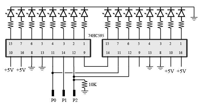
Careful with that schematic - I changed around the pin numbers on the chips to make the diagram more readable. Now you have as many LEDs as you need (keep that board around for Christmas!).
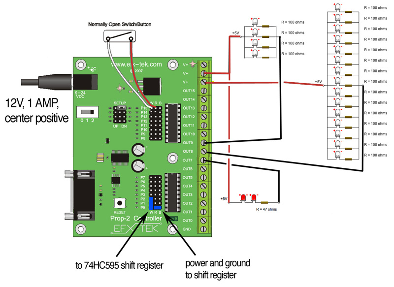
Now for the hookup. The guys from EFX-TEK may have a better way of doing this (they have awesome customer service, by the way) but this was my setup:
And here is the program I used for my haunt. It is significantly more complex than the program above and I will now assume you know how to program rather than explain each command. I do have plenty of comments, though, to wlak you through what is going on. Note that this programe in Basic Stamp V2 whereas the program above is Basic Stamp V1 (They are pretty similar if you stick to the simple stuff. Version 2 let's you handle more complicated programming).
' {$STAMP BS2}
' {$PBASIC 2.5}
' -----[ I/O Definitions ]-------------------------------------------------
Trigger PIN 15 ' SETUP = DN ' define trigger
LedsCenter PIN 9 ' these are white LEDs in the top light panel to light the elevator room
LedsOuter PIN 8 ' these are more white LEDs in the top light panel
LedsRed1 PIN 7 ' these are red LEDs under the sliding elevator door to look like Hell approaching
Latch PIN 1 ' latch 74HC595 outputs
Clock PIN 2 ' shift clock to 74HC595
Dpin PIN 0 ' data pin to 74HC595
' -----[ Constants ]-------------------------------------------------------
IsOn CON 1 'defining a constant so that IsOn turns on a LED
' -----[ Variables ]-------------------------------------------------------
state VAR BYTE ' program state
timer VAR BYTE ' for input debouncing
level VAR BYTE ' for LED brightness
tick VAR WORD 'timer
floors VAR WORD ' define floors as a word (variable). This can control up to 16 floors
' -----[ Initialization ]--------------------------------------------------
Reset:
OUTS = %0000001100000000 ' Initial state has white LEDs in top light panel on (PINs 8 and 9).
DIRS = %0011111111111111 ' this defines PINs 14 and 15 as trigger inputs and all others as outputs.
state = 0
timer = 0
Setup:
HIGH LedsOuter
HIGH LedsCenter
floors = %0000000000100000 ' 1st floor indicator on. Do not confuse floors with OUTS. They are different variables. Floors controls the floor indicator pannel only
' -----[ Program Code ]----------------------------------------------------
Main:
GOSUB Update_Floors 'this subroutine reads the bits in the "floors" variable and pushes it to the 74HC595 chip.
BRANCH state, [Get_Trigger, Run_Elevator, Wate_Reset, Reset_Program]
GOTO Main
Get_Trigger:
timer = timer + 20 * Trigger ' scan input
IF (timer > 100) THEN ' wait for valid trigger
state = 1 ' advance state
timer = 0 ' clear for next state
ENDIF
GOTO Main
Run_Elevator:
floors = %0000000100100000 ' UP light and ground floor lights are on
GOSUB Update_Floors
PAUSE 8500
floors = %0000000101000000 'floor indicator to 2
GOSUB Update_Floors
PAUSE 10500
floors = %0000000010000000 'floor indicator to 3
GOSUB Update_Floors
PAUSE 12500 'durring this pause, an evil voice comes booming through the floor and says that he wants you. The elevator screetches and changes direction
floors = %0000001010000000 'down light on
GOSUB Update_Floors
PAUSE 4000
floors = %0000001001000000 '2nd floor down
GOSUB Update_Floors
PAUSE 10000
floors = %0000001000100000 '1st floor down
GOSUB Update_Floors
PAUSE 2500
GOSUB Flicker_Lights 'this subrutine makes the top light pannel flicker, then shut off.
PAUSE 10000
floors = %0000001000010000 '1st hell floor
GOSUB Update_Floors
PAUSE 7000
floors = %0000001000001000 '2nd hell floor
GOSUB Update_Floors
PAUSE 6000
floors = %0000001000000100 '3rd hell floor
GOSUB Update_Floors
GOSUB Fade_Up_Red1 ' this subroutine fades on the led lights
floors = %0000011000000010 '4th hell floor
GOSUB Update_Floors
PAUSE 6000
floors = %0000000000000001 '5th hell floor
GOSUB Update_Floors
state = 2
GOTO Main
' -----[ Subroutines ]-----------------------------------------------------
' Transfers the contents of 'floors' to 74HC595s
' -- floors 1 to 8 are connected to the 595 chip closest to Prop-2
Update_Floors:
SHIFTOUT Dpin, Clock, MSBFIRST, [floors.BYTE1, floors.BYTE0]
PULSOUT Latch, 1
RETURN
Reset_Program:
OUTS = %0000001100000000 ' LEDs on
state = 0
timer = 0
floors = %0000000000100000 ' 1st floor indicator on
GOSUB Update_Floors
RETURN
Flicker_Lights:
PAUSE 1000
LOW LedsOuter
PAUSE 500
LOW LedsCenter
PAUSE 50
HIGH LedsCenter
PAUSE 50
LOW LedsCenter
PAUSE 200
HIGH LedsCenter
PAUSE 400
LOW LedsCenter
HIGH LedsOuter
PAUSE 600
HIGH LedsCenter
PAUSE 100
LOW LedsCenter
PAUSE 50
HIGH LedsCenter
PAUSE 50
LOW LedsOuter
PAUSE 150
LOW LedsCenter
PAUSE 250
HIGH LedsCenter
PAUSE 100
LOW LedsCenter
RETURN
Fade_Up_Red1:
FOR tick = 0 TO 255
PWM LedsRed1, tick, 20 'fade up red LEDs in 6 seconds
NEXT
LedsRed1 = IsOn
RETURN
Wate_reset:
timer = timer + 20 * Trigger ' scan input
IF (timer > 100) THEN ' wait for valid trigger
state = 3 ' advance state
timer = 0 ' clear for next state
ENDIF
GOTO Main
' -------------------------------------------------------------------------
Now, we have all the lights working. Here is the sound file I synchronized it to. Notice the use of the stereo speakers. One was in the ceiling, the other in the floor.
On to the next part...